Vector GPS system
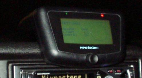
The original Vector GPS system is used to point into the direction of the destination. The information of the destination is programmed using a car phone, the main processor determines the direction from the current position, indicates speed, position and time. This processor gets its information from a GPS receiver module which communicates with a binary protocol to the main processor, unfortunately this is not the most common GPS data, it is a 9600baud data stream with only numbers and no readable text.
To make the GPS data useful for external devices the data must be translated to a standard NMEA protocol, this will be done here by PIC processor. With the NMEA output the Vector GPS can be used for APRS and several PC programs such as Route66, Microsoft autoroute, Navigis, Seaclear and Easytravel.
Components needed
The GPS will remain in original state, the added conponents are:
- 3* 12k resistors
- 1* 4k7 resistor
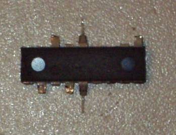
- 1* BC557 transistor
- 1* PIC processor
PIC processor
The PIC processor is connected to the data output of the GPS, external clock, supply and the level converter to the serial output. The PIC is a regular PIC16F84 or compatible, this is the firmware.
All other pins are unused and programmed as inputs. Pin 6 has been used for debugging only, this output is high when sending data and low when receiving data from the GPS. This pin is not needed but may not be shorted…
The most easy location of the PIC is the large connector next to the antenna while all connections needed for the PIC are availble at this location.
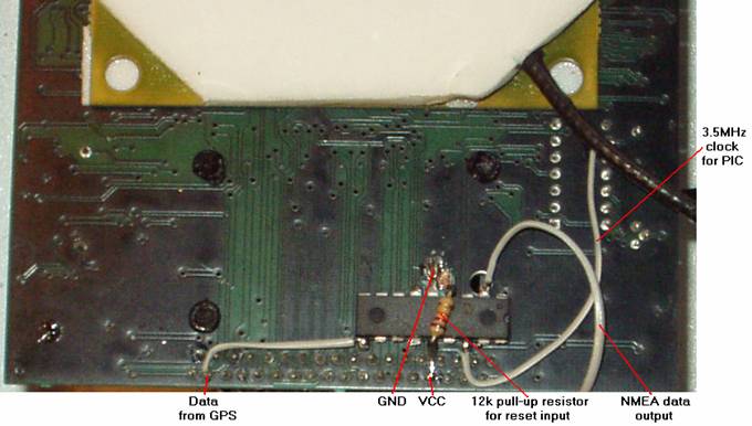
The VCC (+5V) to the display part goes through the 4th pin from the right, the PIC can be soldered directly at this point.
This is the same for the GND, by removing the varnish, pin 5 of the PIC can be soldered at the ground. These are the only 2 pins fixed directly to the PCB.
The data output from the GPS is available at the second pin from the left, the first row. This is the 9600baud serial data at 5V level which goes to the PIC.
A 3.57MHz clock is needed for the processor, this clock is already available at pin 9 of a ‘TDK’ chip, the oscillator part.
The 12k resistor is needed as pull-up for the reset input of the PIC, it must be place between VCC and pin 4.
The last connection of the PIC is the NMEA data output, at this point still 5V level. It will be converted and connected to pin 2 of the com port.
Remove the unused pins first to prevent shorts to the other connector pins… Don’t cut the supply pins 5 and 14 because they will be used to fix the PIC to the board.
Level converter
The 5V NMEA output must be inverted and shifted to a negative voltage for RS232 standard. This simplified level converter uses the –10V of the LCD display, the best solution is still a MAX232 but this simple circuit works fine on laptops.
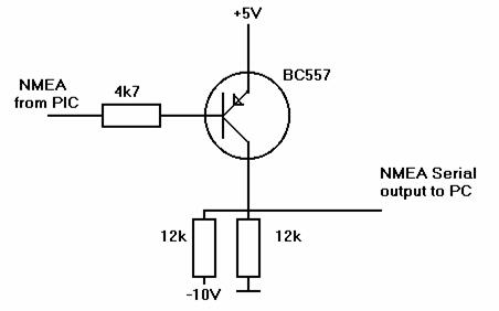
The two 12k resistors are dividing the –10V to –5V for a logic 1 at the NMEA output of the PIC, in this case the BC557 is not conducting. When the PIC’s output is a logic 0 the transistor will be open and pulls the –5V to +5V.
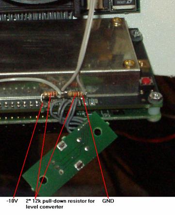
The pin at the right of connector JP8 is the –10V output of the LCD display, this voltage goes to the VEE input via the contrast potmeter at the main board. This point must be soldered to one 12k resistor, the other side to the second 12k resistor, the other side of this second resistor must be connected to ground. There is a hole in the main board next to the metal cap, this is a good place for the ground.
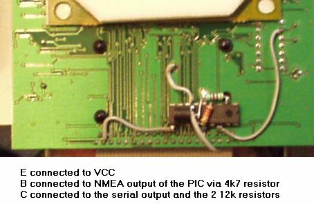

The transistor must have the +5V supply on its Emitter input, the same point as the VCC of the PIC and the pull-up resistor for the reset. The pin in the middle (B) is the NMEA output of the PIC via the 4k7 resistor, the 3rd pin C is the output to the serial port together with the twe 12k resistors on the other board.
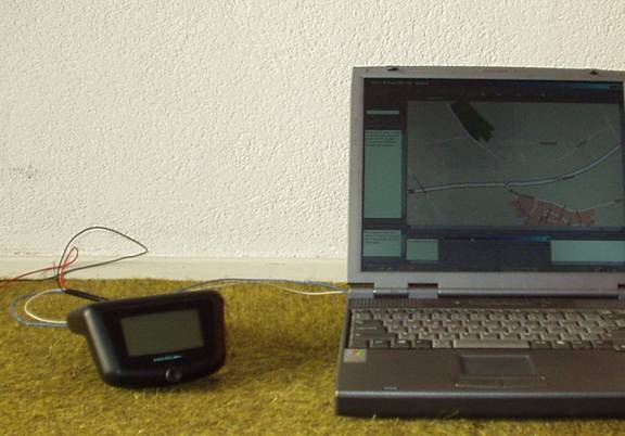
Laptop in the Car or Boat
The connection between the GPS and the laptop is done by the serial port, this is a 9 pin sub-d connector in most cases. Only connecting the RXD (pin 2 of the 9 pin sub-D) and the GND (pin 5 of the 9 pin sub-D) is enough, the PC doesn't have to send data to the GPS.
Connecting the ground is, of course, very important. The GPS is connected to the 12V supply of the car or boat, if the ground of the laptop is floating, the voltage difference between GPS and laptop can cause damage to the serial port! This is also a problem when using a voltage converter to 220V and the original converter of the laptop, never unplug the GPS before disconnecting or switching off the converter. While unplugging the GND may disconnect earlier than the RXD signal, in this case the (very high) leakage voltage will flow through the comport. I had to replace my MAX3243 once...
Be aware of converters which can fed the laptop directly from the 12V, some converters generate a negative voltage and just swap the polarity! In this case the ground of the laptop is a negative voltage betwee -15V and -20V (the voltage of the laptop). This means the ground of the serial port is also negative, when connected to the real ground in the GPS the converter is shorted, this (high) current will flow through both the laptop and gps. If you want to use such a converter, check if the ground of the 12V input is directly connected to the ground of the output with a resistor meter before buying the converter.
Output
The complete data is sent once in two seconds, sending all lines at once is takes too much time for the PIC.
$GPGSA,A,3,6,30,,22,,,,,,,25,,,,*2E
$GPGSV,3,1,12,4,,,41,30,,,38,17,,,0,22,,,34*70
$GPGSV,3,2,12,15,,,0,10,,,0,1,,,0,2,,,26*49
$GPGSV,3,3,12,24,,,0,5,,,0,25,,,42,23,,,0*79
$GPRMC,175018,A,5231.522,N,607.832,E,000.00,000.0,041102,0.87,W*6F
$GPGSA,A,3,6,30,,22,,,,,,,25,,,,*2E
$GPRMC,175019,A,5231.522,N,607.832,E,000.00,000.0,041102,0.87,W*6E
$GPGGA,175019,5231.522,N,607.832,E,1,4,,+5.8,M,46.92,M,,*44
$GPVTG,000.0,T,000.8M,000.00,N,000.00,K*6A
$GPGLL,5231.522,N,607.832,E,175019,A*29
The most common line GPRMC is sent every second for most applications. Only a few applications only use GPGGA, GPVTG and GPGLL, these lines are implemented but only refreshed once in 2 seconds.
The line GPGSA indicates the used satellites, GPGSV gives
the signal strengths of all satellites. The position information of all
satellites is not given by the GPS receiver in this mode.