To the mainpage.
FM1200 mobile
radio.
There
are several different types of this mobile radio. The modification kit has been
tested for B0, K1, STM22 and STM23 versions. It is possible to use VCO steps of
5, 6.25, 10, 12.5 and 25kHz, with the new control software the radio has 100
memory channels with name of max. 23 characters which are programmable with the
keypad of the radio. For digital types, a hardware modification is needed for
generating and receiving tones for sel-call. The controller used for the
internal (trunkin) modem, is now used for generating DTMF, CTCSS and gererating
or receiving single tones as sel-call and 1750Hz burst. Some wires on the
printed circuit board for the modem, must be cut. These are outputs of the
controller, the controller gives the tones to transmit on these outputs. The
interrupt input of the controller is used for measuring frequency of a tone
from the receiver. The signal of the receiver is amplified by an opamp in
open-loop, this is done by removing the 22k resistor, the received audio
results in a square ware for the interrupt input of the controller. The
controller measures the period time of the falling edges on the input. If the
period is the same for eight times within a certain range, the period will be
send to the main controller which calculates the frequency. Most functions are
inplemented in the main controller, the tone controller software has to be very
fast to get a reasonnable resolution. Another duty of the tone controller is
transmitting CTCSS tones, this requires speed. Because the CTCSS tone is mixed
with the audio signal, the tone should stay below the 250Hz and may not give
any harmonics. To generate an as good as possible sine wave, the controller has
to produce as many samples as possible. An DA converter is a good solution, but
the controller hasn't enough outputs and connecting an ADC is a lot of
soldering work and wires. The tone controller generates PWM pulses, the
modulation is the sine wave for CTCSS. The frequency of the square wave is a
several times higher than the sine wave itself, this makes filtering very easy.
The controller runs a program of 17 lines which uses a look-up table for
setting/resetting the output. Every CTCSS tone has another look-up table.
For
this modification are 2 to 4 ROM chips nescesary. The EPROM in the display unit
has to be replaced, this is a small program which does nothing else than
printing the data from the FM1200 to the display and sending the last pressed
key to the FM1200. This software has to be programmed in a 27C128, a 27C256 or a 27C512 EPROM. De EPROM
of the main controller must be replaced and the 24C16 can be replaced by a
24C64 or a 24LC128 to use longer names an tone-codes.
The
last EPROM is for the tone processor, this is only nescesary if tones are used.
It is the SMD EPROM behind the plastic cap, to remove the EPROM, it is better
to cut all pins to save the board. The software for this CPU has to be programmed in a 27C256 or a 27C512 EPROM in SMD
socket. Smaller EPROM's have a different pinout.
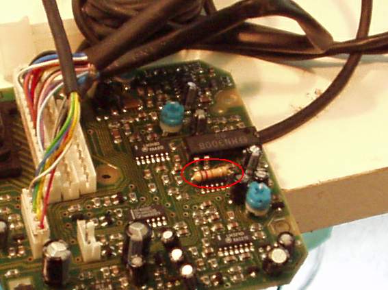
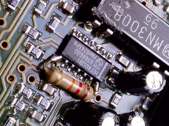
This
is an example of mounting the extra components:
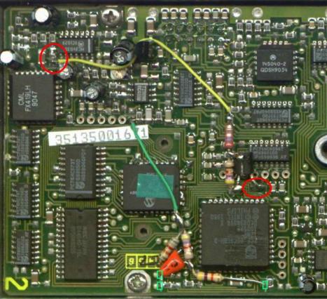
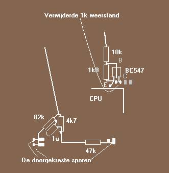
The
SMD components at the red circles have to be removed. At the top, left, a
resistor of 22k, and on the right a 1k resistor. The green squares are
indicating the wires to cut. Another resistor need to be soldered to the pad of
the SMD resistors
* The first startup of the software will reset the contents of the EEPROM, it is set to 70cm.
For 2m radio's the band has to be changed in submenu 'User'.
* One of the two communication lines between tone CPU and main CPU are not routed on CPU board version 1.
In this case, you have to make a connection between pin 17 of the main CPU and pin 14 of the tonecpu to get tones working.
* If the EPROM socket on the CPU board has 32 pin instead of 28 like an 27C512, pin 1, 2, 31 and 32 must be left open.
The EPROM must be placed as far as possible to the display unit.
There is a small description of the data stored in the EEPROM available
here.
Some FM1x00 owners are using a VOX unit in the car, the VOX circuit can be use as an hold circuit for the PTT key by soldering
1 resistor of 12k between the two other pins of this IC:
Please refer to the usermanual for
functions and how to use them, an English version is available at the bottom of
the page.


Display.bin Tonecpu.bin FM1x00.bin
27C128 or 27C256
PLCC package or
27C512
27C256 or 27C512
PLCC package
27C512
To the mainpage.
* One of the two communication lines between tone CPU and main CPU are not routed on CPU board version 1.
In this case, you have to make a connection between pin 17 of the main CPU and pin 14 of the tonecpu to get tones working.
* If the EPROM socket on the CPU board has 32 pin instead of 28 like an 27C512, pin 1, 2, 31 and 32 must be left open.
The EPROM must be placed as far as possible to the display unit.
There is a small description of the data stored in the EEPROM available
here.
Some FM1x00 owners are using a VOX unit in the car, the VOX circuit can be use as an hold circuit for the PTT key by soldering
1 resistor of 12k between the two other pins of this IC:
Please refer to the usermanual for
functions and how to use them, an English version is available at the bottom of
the page.
Display.bin Tonecpu.bin FM1x00.bin
27C128 or 27C256
PLCC package or
27C512
27C256 or 27C512
PLCC package
27C512
To the mainpage.