PI6MEP ATV station Meppel
In the beginning of
2006 a group radio amateurs planned to upgrade the ATV repeater of Meppel. The
previous repeater was pretty straight forward, one input frequency at 1252MHz
and an output at 2352MHz. There was room for an input at 10GHz but was never
actually used.
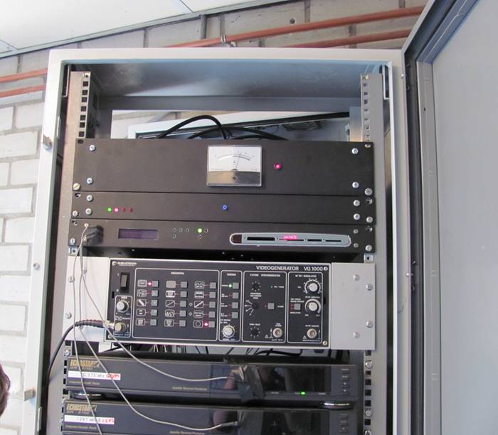
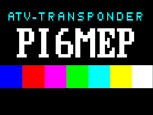
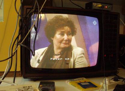
The station used
a videotext generator as test image, controller:
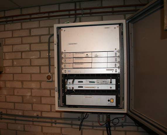
The new station
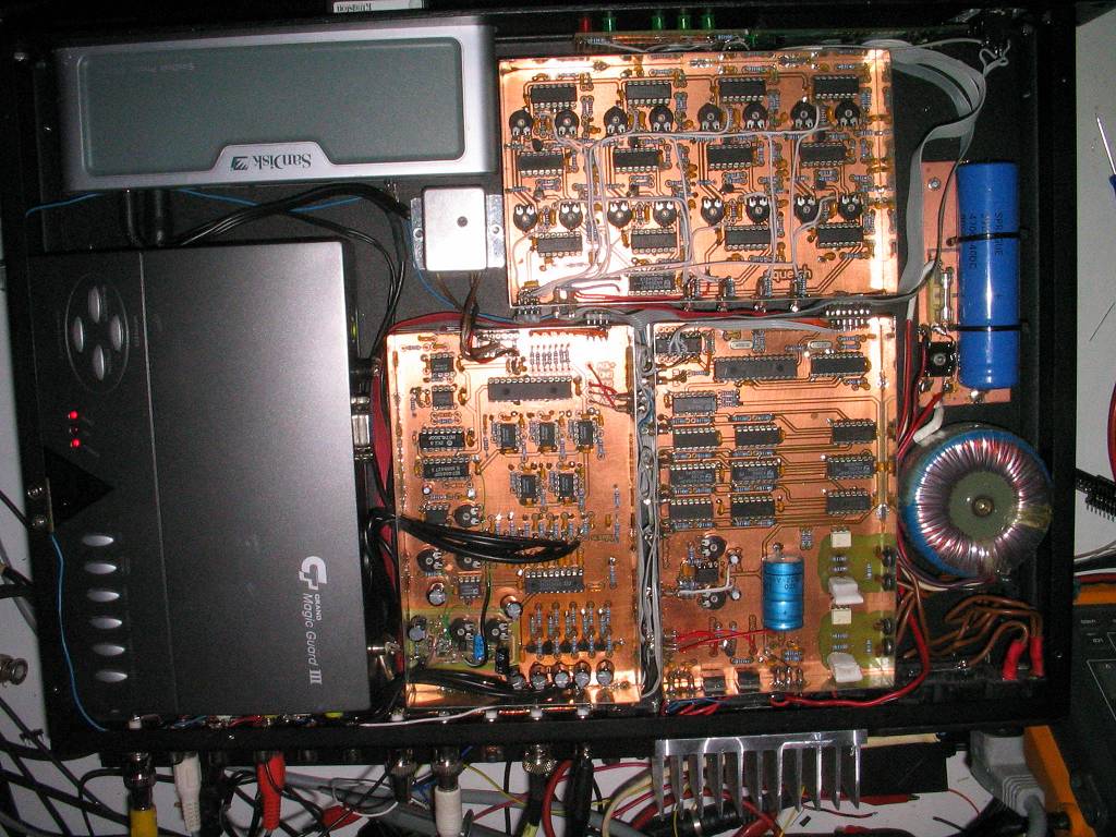
was designed for 4 video inputs. My task was designing the control unit for the
station and the interfacing between the units, people involved by the project
were PE1RDX (antenna and receivers), PA5RJ (PA and antenna), PA2HOS (video
modulator) and PA3FEX (baseband and reference oscillator). The baseband unit
was an existing design, we all did some measurements and improvements
concerning the modulator. Receivers are standard Barco receivers, they have
good specs so there is no need to try to make a better receiver. As soon 2 or
more valid signals are received, the ‘Magic Guard’ unit is used to display both
inputs. The empty display’s are filled up with the image of a professional
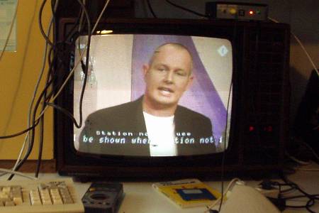
Video test generator VG1000.
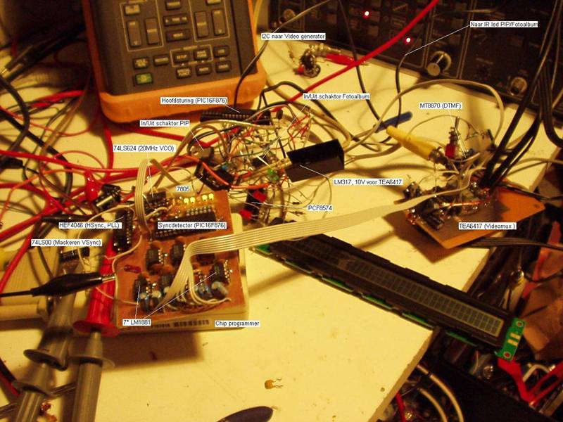
All video and
audio inputs are monitored by one PIC16F876, video is valid if the sync
requirements are met. The PCB on top is a squelch circuit to monitor the audio
channels. There are 2 audio channels per input frequency, one audio carrier of
6MHz and another at 6.5MHz. If only one channel is transmitted by a user, the
contol unit will repeat the audio information of that single channel to both
carriers anyway.
If there is no
video at all at one of the inputs of the station, a slide show is shown. There
is a list of DTMF commands
*1 à Monitor 1252MHz
*2 à Monitor 1287MHz
*3 à Monitor 10200MHz
*4 à Monitor 434.25MHz
*5 à Freeze image (using QUAD unit)
*6 à Show testimage from VG1000 à Use DTMF to change different test patterns
*7 à Force QUAD mode, open squelch
*8 à Connect AUX to 6.0MHz audio channel
*9 à Mute menu à See below, use DTMF to enable or disable video or audio
Mute menu:
1 à Toggle displaying 1252MHz video
2 à Toggle displaying 1280MHz video
3 à Toggle displaying 10GHz video
4 à Toggle displaying 434,25MHz video
5 à Mute 1252MHz audio, toggle between carriers
6 à Mute 1280MHz audio, toggle between carriers
7 à Mute 10GHz audio, toggle between carriers
8 à Mute 434,25 MHz audio
0 à Stop mute and block, back to default
Any other à Exit to main menu
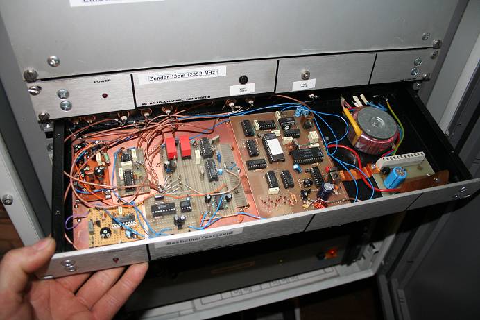
 The
DTMF commands are decoded by a PIC contgroller, this controller act like a
remote control using an IR led in fronr of the QUAD unit (Magic Guard). DTMF codes regarding the videogenerator are send
to the VG1000 via I2C. The VG1000 is not remotely controllable from origin, but
with a number of transistors in parallel with the microswitches on the front of
the device there are a lot posibilities.
The
DTMF commands are decoded by a PIC contgroller, this controller act like a
remote control using an IR led in fronr of the QUAD unit (Magic Guard). DTMF codes regarding the videogenerator are send
to the VG1000 via I2C. The VG1000 is not remotely controllable from origin, but
with a number of transistors in parallel with the microswitches on the front of
the device there are a lot posibilities.
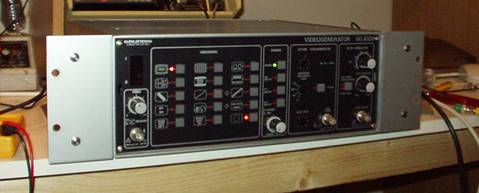
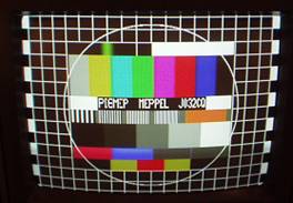
The
identification of the Video Generator itself is programmed in an EPROM. Here is a tool for editing.
Inside the
control unit of the relay station is a second PIC16F876 which synchronizes its
own clock with the actually displayed video signal in order to oberlay text
messages. The task of this controller is to display the station’s
identification and some status messages.
The station has 4
analog TV inputs at 1252MHz, 1280MHz, 434.250MHz and 10.2GHz. The 434.25MHz
input has only one audio channel at 5.5MHz, this is the most common standard in
Europe, kind of upper sideband with frequency modulated audio at a
5.5MHz.carrier. One spare audio input is connected to a handheld receiver for
eventually linking the audio of the local UHF repeater PI2MEP.
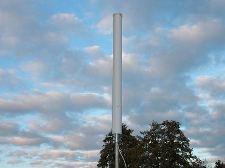
23cm receiver antenna, 1252MHz and 1280MHz 13cm transmitter antenna, 2352MHz
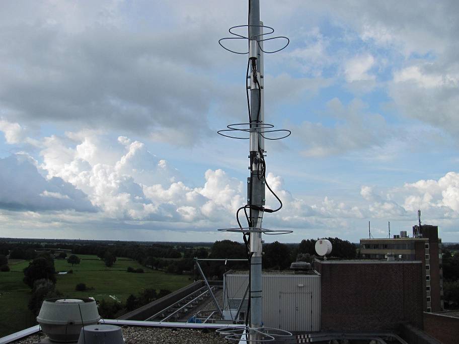
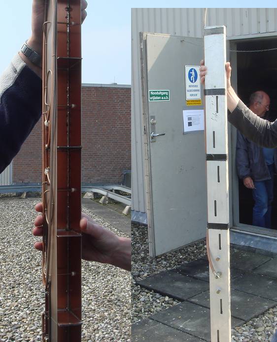
70cm receiver antenna, stacked ‘big wheel’
antennas. (PE1RDX)
10.2GHz receiver antenna, a slot antenna mounted
on the LNB directly (PA5RJ)
PI6MEP in 2010: