To the mainpage.
RS9044 basetransceiver

A few years ago the Dutch telecom company disabled and removed their ATF2 and ATF3 mobile telephone systems. The RS9044 and RS901 were used as basestations for this mobile phone systems. The RS9044 became available for amateur use in the Netherlands and Belgium mainly. Later, i heard about RS9042 and RS904D in France and RS9045 in Sweden. On the bottom of this page are two English documents, the modification is based on the RS9044. The new amateur software software has been tested with the RS9044, RS901, RS9042 and the RS9045.
Please see the
modification
page for the EPROM replacement.
For people who are interested in the original configuration, i have retuned the original software to 430-435MHz for
RS9042
,
RS9044 V0/1
,
RS9044 V3/4
,
RS9045
and the VHF version
RS9160
. This software is not perfect for amateur use.
The RS901 is a 900MHz radio and is almost identical to the RS9044.
The RS9042 is about 420MHz. Compared to the RS9044, the RS9042 has no modem, no 7-pole filters and a backuped SRAM.
This seems to be the same for the RS904.
The Swedish version RS9045 has an internal reference oscillator, mounted on a board and placed next to the IF unit. The RS9044 doesn't have an internal reference oscillator at all. An other nice advantage is the second receiver of the RS9045, switching between the receivers is done by an extra
PCB
.
Several amateurs are using this radio as a relais station, at least two of them are using a different modification for the filter part. The first i knew was John PA3HGQ, the sysop of PI2FLD in Almere, indipendent of John a German amateur Kai Siebels was doing almost the same modification. John removed the cap of the filter and created a new inductor, using the same type wire, but only about 1cm longer. Kai made a
The
modification
on this page is very easy and has most possibilities due to the used software. More than 50Watt at 70cm
The software can also be used independent of the modification or in combination with other hardware modifications, there are three known possibilities to modify the filters.
The meaning of this modification was to keep the RS9044 in original state, as far as possible. Where possible, changes for amateur use are solved by software.
Several extra functions are implemented in software for packet and for use as relais station. It is possible to
decode CTCSS
bij using a
FX365
or a
FX335
.
Since the software is most important give the RS9044 any possibilities, i have spent most of the time for writing the software to make it easy to use and to support all hardware. The software is functioning for several years now, the last versions without any problems. The latest version at this moment is 2.8, for normal use no important
changes
compared to version 2.6.
Some information:
Sensitivity: <-6dBuVe at 20dB S/N
Transmitter power: More than 50W continuous
Receiver: 453.000-457.500MHz
Transmitter 463.000-467.500MHz
After modification, the sensitivity won't be worse
and in most situations is the output power about 80W.
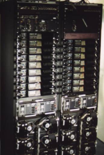
The picture on the right has been taken in
a tower in Smilde, at the moment they were still
in use.

They are provided with a microcontroller, which gives the possibility to configure the RS9044 by the keypad and display. Another duty of the microcontroller is to check VSWR, supply, temperature, AFC etc.
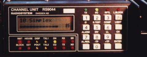 The software and partly the
LF board creates a complete
complete 70cm transceiver
with VCO, 100 memory
channels, call channel,
relay-shift, DTMF, selcall,
CTCSS, VOX, SCAN
possibility, tone suppression,
duplex, callgever and
several repeater functions. The
posible channel spacings are 5, 6.25, 10, 12.5 or 25kHz. The frequencies can be entered by the keypad and a rotary dail can be used. The software has a status menu where temperature, transmitter power, PLL voltage, VCO output level, AFC correction and supply voltages are shown.
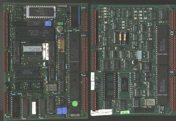
These are the microcontroller boards. There are two different generations, the left is the older generation. The software must be placed in the empty socket.
The use of a rotary dail makes it very easy to configure and select frequencies very fast. Below an example of the mounting of the rotary dail. It is a Bourns
ECW1J-B24-AC0024
, on the location of the test output of the transmitter.
![]()

Information of the modification can be downloaded by a right-button click on the icon, and 'Save link as'.
![]()
![]()
RS Ombouw.pdf RS Gebruiksaanwijzing.pdf
![]()
![]()
English modification English usermanual
To the mainpage.