PAL decoder
After some years i started
using the NMS8280 again for HAM radio purpose. When sending a signal in the air, radio
amateurs should always identify by giving their callsign, this is also the case for sending
a video signal. I wrote a program using the WBASS assembler which shows a scrolltext, this can
be downloaded
here
. Unfortunately the incoming video signal is first converted to RGB, and converted back later after
superimposing. The PAL decoder in this MSX is not very good, the encoder to convert RGB to CVBS is
quite okay.
At first sight the picture improved
by placing a capacitor over the filter just before the PAL decoder, this filter separates the
colour (c) (4.43MHz) signal from the luminance (y) signal. For the y path, the video signal is
passed through a lowpass filter which starts attenuating around 3MHz... This gives loss in
sharpness. I tried to improve this filter, but it's not easy to keep the delay of the y and c path
equal, and too high frequencies will give aliasing while digitizing.
Another work around
is to simply switch between the unconverted inputsignal and the signal coming from the MSX video
processor after the PAL encoder. This can be done by a 4053 for example. Normally the internal
PAL encoder from the MSX will switch between the RGB signal of the MSX and the RGB version of the
incoming video signal. The MSX video processor (VDP) determines when to display the internal or
external signal. When this signal is used to switch the CVBS signals with the 4053, we are done
for 80%...
The select signal
from the VDP is related to the RGB output of the VDP, after converting to CVBS the signal
will be delayed for about 200ns. A 74HC74 is used to delay this digital select signal 2 clock
cycles of the DHCLK of the VDP, otherwise the 4053 would switch too early. For example one
white vertical line from X=100,Y=0 to X=100,Y=200 will result in superimposing a black line
at X=99.
At the beginning of
a line a short pulse of 4.43MHz (burst) is given to synchonisse the PAL decoder
inside a monitor or TV. Both CVBS signals are synchonised in the sense that the line
number and the position in the line are corresponding, but not really for this
colour signal.
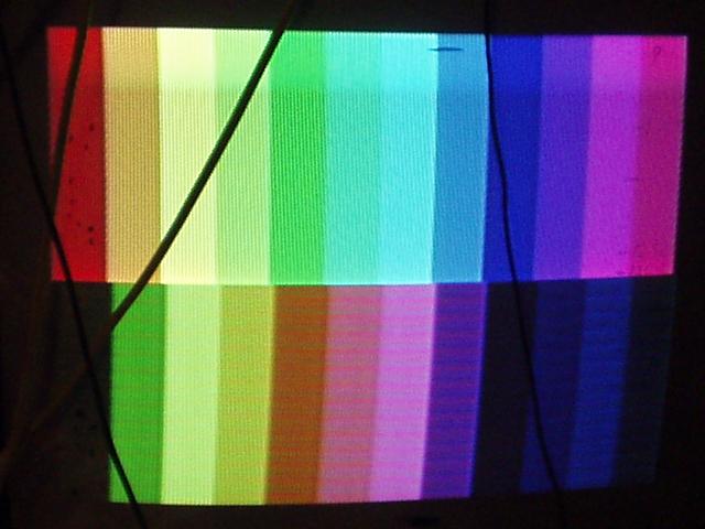
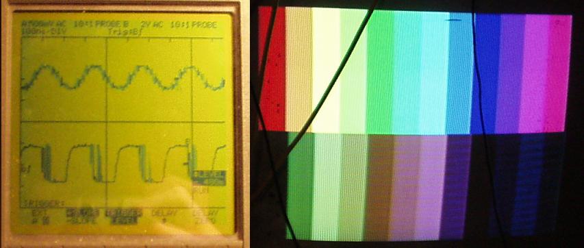
Picture of superimposed signal (Sorry for the cables in front of my TV...) The strange thing is, when the phase is
wrong you would expect an inversion of both red and blue. In this situation blue seems okay, but only
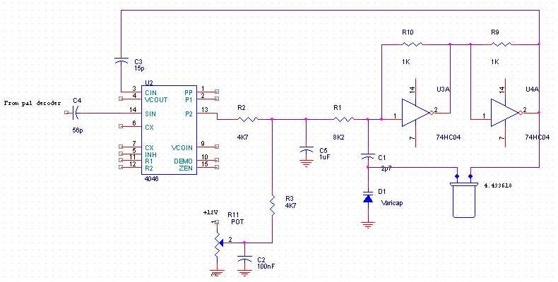
red inverted. To get a clear idea of what happend i made a small, simple circuit to be able to create
any phase shift of the 4.43Mhz signal using a PLL.
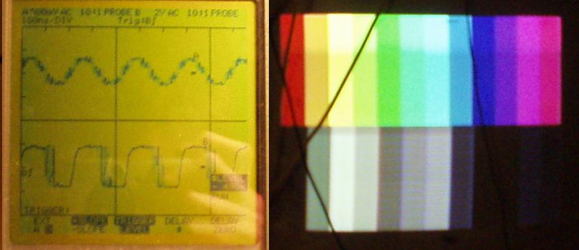
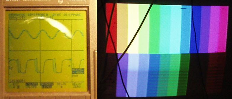
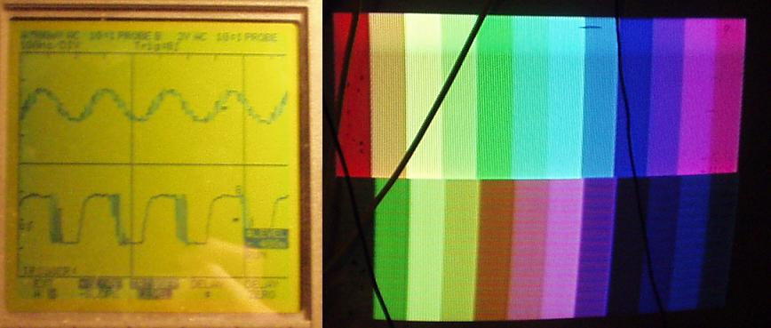
I took four pictures
of some phases and the resulting colours, after that i had to spend some time thinking...
The last one has
the best colour saturation, in there is a phase error the colour intensity will
be less. The second one has different colours but still not right. After taking a
closer look into a schematic of a PAL decoder, the phase of only red turned out to
be shifted from line to line the wrong way. The PAL encoder turns the phase in exactly
the opposite way compared to the input signal. Inverting the H/2 line between
decoder and encoder solved this. To finish, a small phase correction to the encoder
optimizes the colour.
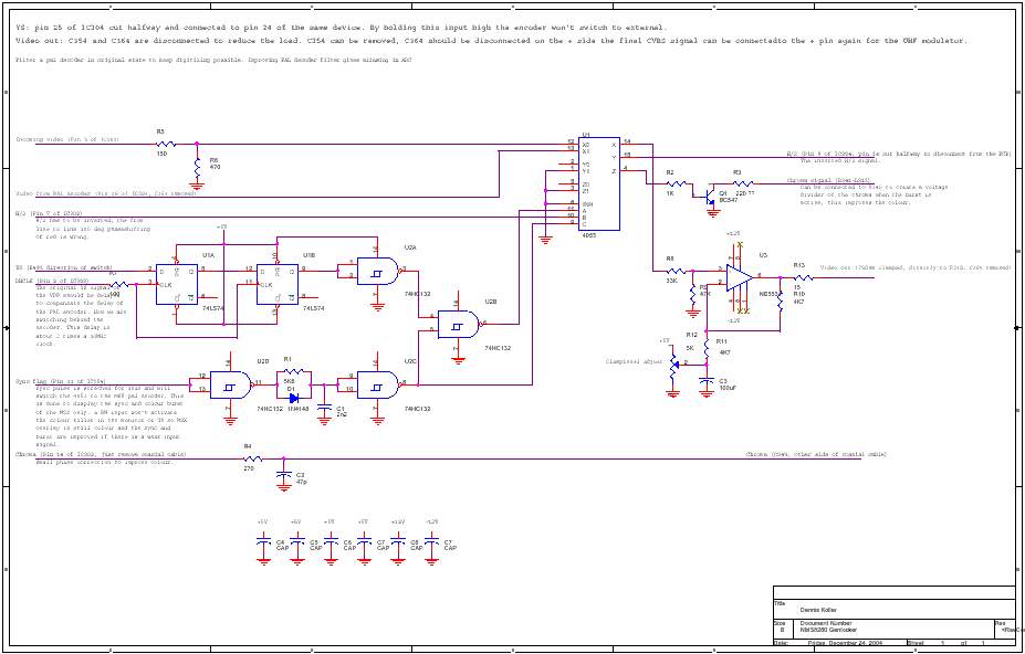
When comparing the
original signal and the signal which is routed through the MSX, there is still
some lack of colour. To solve this, the burst is attenuated by pulling it to ground
by a transistor trough a 220Ohm resistor after the 1k resistor. The colour signal
is coming out the PAL encoder, through a 1k resistor and an inductor. It is mixed
with the y signal later on. After this resistor the colour signal is pulled low
during the colour burst. Due to a weaker colour burst, the colour will be increased,
because the colour signal during the rest of the line is stronger compared to the
reference, which is the burst.
The
final schematic Timing
Colour synchronisation